Tips and Tricks
User know-how
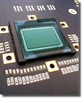
Color CMOS sensor
Environment illumination provided as standard in an
office or in a production hall is almost sufficient for most
black-and-white video high-speed camera systems. They have
sensitivities somewhere between about several hundred and several
thousand ASA at nominal frame rate depending on amplification.
Color versions usually show about 25% of that only.
The special features in comparison to standard imaging mainly
derive from the usually short exposures and the working close to
limits - physical and technical ones.
Otherwise obviously the usual photographic rules, restrictions
and, of course, possibilities are valid.
Tips for shooting
Illumination, aperture (f-stop) and dynamic
Evidently it is valid: everything counts in large amounts.
The more light is offered the more the aperture can be closed, i.e.
a higher f-stop number can be set, enhancing the depth of field. At
f-8 or higher it is well done, but 5.6 is sufficient enough.
Usually there is never too much light - it is possible to shoot the
glowing filament of a 500 W tungsten bulb, the hot spot during
laser welding or an electric discharge. (Caution, directly viewing
in the laser beam is then too much of a good thing.) Only the
brightness dynamic of the camera is problematic. That is just valid
for all electronic cameras. Good to notice when making a photo
looking outside a window deep from the room. (Therefore in
interviews in office rooms one prefers to shut the curtains or
jalousie. Besides then the spotlights are not so intensively
reflected. Until HDRI (high dynamic range image) is widely spread
some time will pass.) The usual 8 to 12 bit or 256 to 2 048
brightness levels, should be optimal used, even if 64 gray tones (6
bit) provide a sufficient quality. If one wants to image the less
illuminated environment, one will have to light it up. Comparable
to the additional (background) light-up flash in photography.
Just to mention, if it is too bright at all, (neutral density,
short: ND; i.e. neutral, colorless) gray filters will offer help.
Or selective filters, which e.g. dim the wavelength of a welding
laser, but not those of the weld deposit. Many lenses provide
threads for that reason.
Practice-oriented example: if one wants to image the sparkles of a
cigarette lighter together with the holding hand, about
1 000 W will be necessary (see sample 2 with and 3
without lighting up in [SloMo Clips]).
By the way: the dynamic range is often given in units of decibel
[dB]. The connection to bits and bytes gets clearer with the
following formulas:
x [dB] = 20 × log y and y = 10x/20, resp.
In which x represents the value in dB and y the number of
sensitivity steps.
Thus 8 bit (= 28 = 256) make so 20 × log 256 =
48 dB, while 60 dB stand for 1060/20 =
1 000, so for about 10 bit (210 = 1 024) dynamic
range. Thus 12 bit would be about 72 dB. These are typical values.
As technical expression here the term signal to noise ratio is to mention. It indicates how much stronger the useful signal »exposed image« is compared to parasitic effects - not in the latest charges of a pixel (in real a photocell; ~»solar cell«) are even spontaneously and arbitrarily generated without any illumination but caused thermally only. And the term full well capacity indicating how much charge a photocell can generate at all until saturation takes place, thus more incident light does not generate further charge carriers. Here large area pixel show their advantage concerning dynamic.
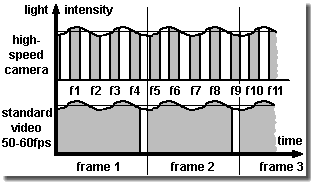
Click for flicker illumination effect: [SloMo Freq.]
More about light -
Photo hf:
Photo
Professionals use at least halogen spots in studio quality
(defined color temperature ...), cool beam reflectors (with
reduced IR spectrum), or even HMI spots (daylight spectrum) and DC
illumination devices (rectified) to avoid the jitter of the
50 Hertz or 60 Hertz, resp. (1 Hz (Hertz) = 1/sec), power
supply frequency.
There are obviously lamps switching on and off during operation
and one usually does not take notice of it. Even light emitting
diodes (LED) can flicker, partly unintended due to a not sufficient
enough stabilized DC power supply. But partly also intended - the
maximum current, and thus the (momentary) brightness of the LEDs in
flash mode, is namely allowed to exceed that of continuous
operation by far. (Suitably synchronized they are appreciated
because of their lack of radiate off heat.)
A sequence mainly illuminated by common fluorescent tubes therefore may
show distinct pumping brightness, see the figure on the left
and for details see [SloMo Freq.]. The
effect is also known from flickering slow motion replays on TV broadcasts.
(Obviously there were some reasons for the good old light
bulb. ;-)
Due to the different color temperatures of light sources, e.g. the
tungsten filaments of halogen lights shine with longer wave-length
or warmer (i.e. more yellow,reddish) than daylight, electronic
cameras offer a so-called white balance feature. Then white will
become pure white again.
And caution: a halogen spotlight with a nominal power of
1 000 W heats with about 900 W. This might be
sufficient enough to melt plastics within a distance less than
1 m after a while!
Exposure and aperture (f-stop)
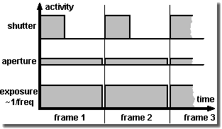
Function of shutter and aperture (f-stop)
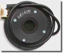
Liquid Crystal shutters using Displaytech's FLC types.
Designed for external or internal mount.
Supply and control by the camera electronics.
Exposure, better the maximum time of exposure, of most high-speed cameras, is nearly 1/frame rate. With e.g. 1 000 frames per second, thus the time of exposure cannot exceed 1/1000 second. The sensor is integrating (= gathering) over the incoming illumination during this span of time.
In fact the sensor is ready for shooting during the whole time
of exposure of one single frame. The gray areas under the curves in
the upper image on the right give a measure for it. The narrow gap
between the frames is the read-out and/or initiation time of the
sensor, duration in the range of some microseconds or even
less.
Closing the aperture of the lens (f-stop) reduces the amount of
incident light global for all frames. The bigger the f-stop number
the smaller the iris aperture gets and the less light reaches the
sensor.
A shutter reduces the incident light, too, but by repeatedly
reducing the (fixed) time of exposure of each single frame.
Technical spoken it changes the duty cycle and reduces the
effective time for one single shot or frame.
While the f-stop in general limits the light intensity for
exposure the shutter is mainly used in order to reduce distortion
caused by motion (motion blur). Because if the object is moving
during the time of exposure with more than 10% of its size, this
will be bothering usually. (In still photography one accepts just
up to 3%, if ever.)
There are different possibilities for reducing motion blur:
-
Increasing the frame rate (may cause a decrease of resolution due to camera possibilities and a demand for more light)
-
Use of a stroboscope (where the background illumination must not be too bright and the area illuminated by the stroboscope is limited)
-
Use of an optional shutter, e.g. a liquid crystal shutter (LC shutter), which permits exposure down to about 1/10 000 sec, but causes the loss of two aperture steps even totally opened (transmission typically about 30%).
Many up-to-date systems offer as standard a more than ten times
faster electronic shutter in their chip design and therefore do not
need an additional LC shutter. Exposure times of microseconds and
less are not technical problems, but export topics addressed by
dual use restrictions (military use and proliferation).
For those, who want or need more - in this case shorter exposure
times - a Kerr cell or a Pockels cell, or possibly a microchannel
plate (MCP) can help. Of course, there are mechanical shutters and
choppers in the shape of slit or hole wheels, too.
Annotation: in contrast to the mentioned above global shutter (or
snap-shot shutter, freeze-frame shutter) simultaneously operating
on the whole sensor, there is also a line by line operating rolling or
slit shutter. Concerning movement analyzing one should prefer
cameras with the first one, because the line scanning of the sensor
does not guarantee to take the resulting frame at a defined moment
and according artifacts can occur.
Changing the shutter time one can vary the illumination, of
course, if one is not able or does not want to adjust the aperture
(f-stop) ring. The latest concerns more the artistic approach,
because the depth of field depends on the aperture. It increases
with the f-stop number. Who ever may need it...
Depth of field (or depth of focus)
Expression for the distance region where objects appear
sharp on the image. The reason why it is not just a simple point
like the inscription on the distance ring (focus) seems to claim,
is that within a tolerance area the film, the sensor or one's eyes
do not show resolution enough. When a point is displayed within the
so-called circle of confusion (about 0.01 mm to 0.025 mm
diameter with common sensor formats and 0.033 mm with
35 mm format cameras), one will not perceive the blur at
all.
The position and expansion is mainly dependent on the aperture:
small aperture (= higher f-stop) number - large depth of field.
Where it is larger behind the calculated position of focal distance
than in front of it.
Depth of field increases with shorter focal length and greater
distance to object. Larger film/sensor format exact larger
pixels, resp., however, permit to decrease it. (Due to crop factor
sensor shrinking increases depth of field by force.)
There is a rather bulky formula, see distance and focal
length calculator [SloMo f = ∞].
Anyway depth of field is a no-word in high-speed imaging in industrial
environment (mostly the aperture of the »Dark-o-matic« is just opened
like a barn door. ;-).
Using the so-called hyperfocal distance h the region starting at
h/2 to infinity appears in focus. It is also called fix focus
setting or near adjustment and is especially used with simple
cameras.
Cheap lenses, especially for surveillance cameras, often do not
even offer a focus ring. They are focused by the aperture only.
Here the electronic amplification (gain) of the cameras has to
provide the required brightness.
Field of view and lens
Endeavor to do a good job: image the interesting scene as
screen filling as possible. With C-Mount it is not too tricky to
use spacers (extension tubes in a set for less than
€/$ 50.-) and a fixed focus lens or an additional short
distance lens for covering the entire screen with an object of
5 mm (= 1/5 inch) in diameter. Do not choose a wide-angle lens
with a focal length smaller than 6.5 mm (concerning C-Mount
2/3 inch format) for applications using automatic image processing
(e.g. with object tracking), otherwise distortion would reach a
level not to be tolerated. All lenses and equipment suitable for
the according mount can be used, even filters, macro, zoom and
fish-eye lenses and with appropriate adapters photo lenses,
bellows, microscopes, endoscopes, boroscopes, fiber optics, image
enhancers (night goggles) ... But pay attention to the fact the
more complicate the optics are the more illumination is often
necessary.
Professional photo stores offer adapters to fit common lens
mounts, e.g. C-mount to Nikon bayonet (Nikon F). Some high-speed
cameras (like many professional photo cameras, too) additionally
allow - due to a mounting plate/reference plane - the choice of a wide
range of (customer) specific adapters including popular ones like
Nikon F or C-Mount and others e.g. PL, Kinoptik or Stalex
(M42).
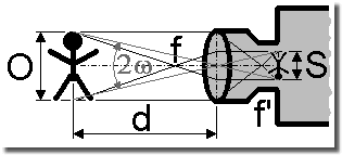
Click for focal length calculator [SloMo f = ∞]
Actually the focal length inscription on a lens is
the focal length at the image side, if imaging an object in
infinite distance with a wave-length of 546 nanometers. Then the
image will appear in the focal point located at the image side of the
lens.
The definition according to DIN 4521 standard is:
f' = limω-->0 (y'/tan ω)
With the half field angle ω and the half
image diagonal y'.
(Suitable for practice subsequent the field angle is simplified to
be the angle of view due to format filling setup and f' and f are
just taken as the focal length inscription of the lens.)
The rule of thumb for a rough calculation of the focal length for a format or a sensor filling image S is
focal length = distance to object / (1 + object size / image size); [all values in mm]
And the estimate of the necessary distance at given focal length is
distance to object = focal length × (1 + object size / image size); [all values in mm]
The angular field of view FOV = 2ω (≡ 2ω', see the figure above) is given by
FOV = 2 × arctan (1/2 × image size / focal length)
The magnification M derives from the imaging through the lens onto the sensor and the display of the image on the monitor or other media
M = focal length / (distance to object - focal length) × diagonal of monitor / diagonal of sensor; [all values in mm]
One must pay attention to the restrictions of standard lenses.
In a distance less than 0.3 m (approx. 1 foot; sometimes even
1 m, approx. 3 feet) to the object they cannot provide sharp
images. In such cases one needs a spacer (= extension tube), an
additional short distance lens or a micro (-scope) lens, and so
on.
The thickness t of the spacer, which is screwed in between lens
and camera body, is given by
t = image size / object size × focal length; [all values in mm]
in which the relation image size / object size is called imaging scale. But caution, just despite of their simplicity - extension tubes swallow light.
Fine adjustment of flange-back (back focus lens adjustment)
Evidently a wrong adjustment of flange-back derives from
manufacture tolerances, mismatch (incompatibilities of components)
and media brought in the beam area between lens and film or sensor,
resp. And concerning crash-proofed cameras mechanical stability is
above all, even above (too sensitive) adjustment mechanics.
Provided that the suitable adapter is selected using a lens of
fixed focal length one easily receives sharp images by turning the
distance ring (focus). Maybe the distance inscription and the
magnification are slightly wrong then. Usually this does not bother
one further more.
Using a zoom lens, however, one looses the sharpness (i.e. focus) of the image
during zooming process. As a rule it should be steady and only
magnification (and thus the angle of view) should change. Then the
zoom lens is only usable in a restricted manner as vario lens. One
is ought to adjust sharpness simultaneously during zooming all the
time. High-speed cameras, however, are rarely used for such zoom
shots.
Nevertheless, in order to take full advantage of the zoom feature
the flange-back has to be adjusted accurately. Using simple tools
proceed as follows:
-
Open aperture as wide as possible to reduce depth of field (if necessary dim the room illumination, reduce time of exposure, ...)
-
Select an object in a distance of about 3 m to 7 m (this is about 10 feet to 23 feet)
-
Gain a sharp image at maximum zoom (biggest focal length) by turning the distance ring (focus)
-
Gain a sharp image at minimal zoom (smallest focal length) by changing flange-back. (Do not turn the distance ring hereby)
-
Iterate until you receive sharp images at both zoom positions without re-adjusting
To adjust flange-back camera housings offer either a thread tube
to be moved back and forth - almost standard with C-mount cameras.
Or metal pads (washers) are fed in between lens adapter and camera
body, if not even mechanics are integrated in the camera body in
order to change the sensor position. There are also lenses,
especially C-mount ones, with a cylinder housing at the camera
side, which can be shifted. Look for a small depth bold at its
circumference.
The IR switch of high-end lenses does nothing different. It quasi
moves the lens away in order to project the IR images onto the
sensor.
Evaluation and measurement
Eminent: please do not forget you receive a lot of data. A megapixel resolution at 1 000 frames/sec and more just leads to data rates in the Gigabyte/sec range. Thus more than a complete CD-R per second would be filled. Per each camera, mind you. (Here at [SloMo Data] you will find the formula to estimate the data amount.) So do not wonder why the high-speed camera system is rather busy, when downloading, saving and viewing these files. And - it is highly recommended to have a storage/backup concept for the files.
The huge data amounts cause the cameras to be used offline. Thus
they are not immediately used for controlling and they are not
directly integrated in a superior machine control circuit. The
image processing would be just too costly and too slow. One watches
the scene and analyzes afterwards.
(Today slower cameras of the image processing sector - »machine
vision« sensors - can already be equipped with a lot of calculating
power, therefore named smart cameras, allowing them to work like a
sensor only providing a simple good/bad signal for the control unit
- e.g. »Label position on the bottle is all right - Yes/No?« - and
not sending image data for further computing.)
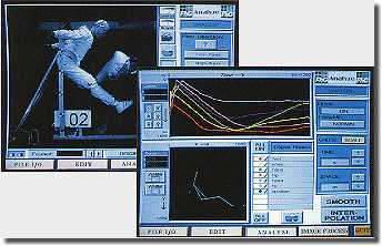
Trajectory evaluation: translation, rotation,
velocity, acceleration and stick-figure animation
For controlling high-speed cameras even multi-channel systems of
different suppliers special software is available. The evaluation is
carried out either directly visual or using motion analyzing
software packages, so-called motion trackers. See e.g. the
links given in [SloMo Links].
To make it easier for automatic motion tracking by software one
should pay attention to ensure a homogeneous background and, if possible, to avoid
gratings, chessboard pattern or something similar (like a wallpaper with
flowers ;-). Thus reducing the calculating time and
preventing the tracking algorithm getting stuck with the attractors
in the background instead of pursuing the desired target.
D-Load
If you intend to archive your image files in AVI format,
consider making use of the compression tools Intel Indeo
or DivX saving up to 90% memory capacity without loosing
too much quality. DivX will often provide smaller files, especially
if less movement happens in the scene. In contrast Indeo commends
itself for automatic image processing, because it manipulates
object position in a smaller extent.
AVI files can be processed (i.e. changing frame format, replay
speed ...) with e.g. video editing soft-/freeware. For these and
other tools just have a look here in the download center,
see the button on the left.
Namely one shoots sequences with super slow motion to slow down
fast movement for visual inspection, nevertheless, one should
create some faster replays, e.g. with 25 to 100 frames/sec (of an
original with 1 000 frames/sec), otherwise the impression of
movement is lost. This will become important then, if one wants to
show the sequences to some outsiders, who are not so familiar to the
scenery.
Because the high-speed cameras run also with a normal speed of 50
or 60 frames/sec it is also possible to shoot true video clips. And
copied on a USB stick with the same replay speed one can hand out
it to the customer the machine has been built for with the words
»So your machine has been working during the final tests«.
Just generating a sophisticated impression, not only with the high
resolution cameras. Thus the test becomes a advertising movie.
Tricks for system integration
Trigger and synchronization
Easy to understand - to trigger means nothing else, but to
start something caused by a single event. For instance the
recording will be started, when the crash test vehicle hits the
wall. The trigger device is often just a simple closing contact at
the bumper providing a short circuit in the impact moment or a
light barrier. (Often a flash light additionally marks »frame
0«.)
To synchronize means to stabilize the frame rate in a defined
relation and a fixed delay towards a repeatedly happening event
during a period of time. Ideally this is done by a recurring
control signal, which causes a frame to be captured each time. So
using a stroboscope as illumination source one will adjust the
record phase of a camera so that it will be in recording mode, when
the stroboscope flashes. So one equals the frame rate and the flash
rate and adjusts the image capture to ensure the camera is active
during the flash, not that its shutter is just closed, thus it is
able to catch the rather short flash.
Sometimes cameras offer a so-called »strobe« control
signal. It marks the phase of exposure of each frame; during the
cameras is in exposure mode, it is set.
Triggering is not as simple as it seems at all. Because the synchronously operating camera has to react on a sudden asynchronous trigger impulse after all. Therefore a capture gap can easily occur, because the camera has to finish the previous image capture before. Due to possibly already writing in the image ring buffer memory when the trigger impulse comes high-speed cameras often do not show a so-called restart capability like video cameras without image memory can offer. The latter are able to start a new frame almost in time with the trigger. Earlier image data are discarded where necessary.)
If one wants to trigger or synchronize various
devices, one will face the problem of different signal levels,
impulse widths and phase shifts not willing to work
together.
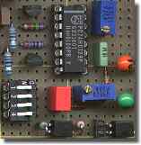
Therefore here on the left side a very simple and cheap circuit,
see [SloMo Trig.] for
explanation, which may be helpful for some adjusting jobs.
(Because not everywhere »Trigger« is labeled, trigger is
really inside. ;-)
Just in multi channel and especially in 3-D measurement applications synchronization between the cameras and their triggering in general becomes extraordinary important.
In frame trigger and external trigger
Engineering and CMOS make it possible. The trigger is released by the frame content as soon as a predefined color change of a certain pixel count surpasses the threshold value in an also predefined region of the (live) image. Elegant, but what to do if it is necessary to react on an electrical trigger signal from outside, but there is no interface available for it - e.g. at the smartphone? Just place a LED into the scene and operate it by the external trigger. That is then the useful trigger region. A small delay may occur. Well, possibly a nice job to measure it?!
Remote control
Exercise: a camera head should be adjusted (scene, aperture, sharpness, shutter, trigger, format ...), but the host PC is in a distance, e.g. in a control room behind a safety door, so that no live image is available near the camera. Or one wants to control the camera system from an extended distance.
The common interfaces (Gigabit Ethernet, etc.) are sufficient
fast enough, but one is often dependent on expensive control
software of the camera manufacturer or a third party
provider. (And WLAN is tricky thing - either the camera is not
equipped with it or one is a little bit scared due to the sensible
data.)
Why you do not just try an inexpensive KVM? A keyboard-video-mouse
extender (or switch) offers an efficient remote control without interfering
with the PC. Even additional driver/software are not
necessary.
The KVM consists of a transmitter and a receiver in the simplest
case connected with a standard Cat 5 UTP Ethernet cable. The
transmitter is plugged to the control host PC instead of keyboard,
mouse and PC monitor. The real peripheral devices are connected to
the receiver. Now one can operate at the receiver as if the host PC
stands beside one's knees. Depending on the chosen
system or transmitting technology, resp., distances of several ten meters up
to some hundred meters and even more are possible.
Meanwhile All Share®, Airplay® or whatever may be a substitute.
Even a WLAN monitor. But do not underestimate the delay for sending
and displaying a frame through air, especially if you want to use it
for triggering by hand. Test it!
Autologon and automatic start
Exercise: a Windows PC with or without Ethernet connection should start alone. In a special case even without connected keyboard, mouse and monitor.
One can bypass the password query using the autologon feature of
Windows. (Attention: after that the password for the system and the
network stands in the regestry.) One creates a new user account
without password query or one sets an exiting account
accordingly.
If desired, put the program (or its shortcut) you want to start
automatically in the Autostart folder to be found in the
Start menu programs.
Additionally activating in BIOS »halt on no errors«
causes the PC not to wait on a feed-back of a keyboard or a mouse.
This will make sense if you can operate the system by a remote
control.
Result: the system runs up to the Windows Desktop, and with your
desired program in the Autostart folder, even up to your
application.
Visit the Windows Help if necessary.
Cleaning lenses, sensors and LC shutters
Experts at work - of course, nobody has grasped on the
lens and even less one has left the lens uncovered until a regular
dust hill has gathered on the top. Blow off would not help yet and
one has too often the impression to distribute the dirt only during
a cleaning attempt at all. Not to mention the risk of scratching
the comparatively sensitive anti-reflex coating, when using a dry
duster.
Alcohol (isopropyl) drenched cotton pads, damp cleaning rags
for spectacles or chamois leather with water thinned dishwasher or
window cleaning detergents (and soft wipe paper to remove their
residues!) are much better. The ultimate tool against fingerprints
and dirt on glass, however, is e.g. First Contact Polymer
(substitutes Opticlean Polymer from Dantronix) - not quite cheap,
but final; or just even use the lens hoods instead ;-).
Usually the sensors of video cameras are protected by a sometimes
coated, i.e. with optical layers, glass plate. Especially in still
cameras and black and white configurations, however, the chip can
be plane open. Then caution should be exercised when cleaning due
to the sensitive color pattern film (polymer) or the sensor
surface and its bond wires. It is highly recommended cleaning the
LC shutter, if ever, with much more sensitivity than one is used to
do so with glass surfaces.
When no voltage is supplied to the LC shutter, it may show spots
and blots making it look spoiled. Do not worry, the operating
voltage will erase them all. You can easily check this by operating
it at the camera with low frequency and trying to look through it.
Or by supplying alternating DC voltage (±5 V? see manual!)
to the shutter and looking through it.) Then it completely opens
and completely closes.
Extend the [TOUR] to images, info and technical data of the SpeedCam systems as an example for the features of digital high-speed cameras.

