Image memory of digital high-speed camera systems
Where to save all the image data?
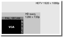
VGA, traditional and new TV formats
Emerging data: already at VGA resolution with 640 x 480 pixels and a frame rate of humble 100 frames/sec more than 30 Megabbyte data are sampled per second. But that's just to handle with standard interfaces and mass storage media, with USB 3.0 even 800 frames/sec. For megapixel resolutions and about 300 frames/sec therefore the frame grabber / control unit approach with the CoaXPress interface. A concept that is never outdated, because the problem getting rid of the huge data amounts is always present.
Image recording and data transmission
Imaging techniques
Existing digital high-speed cameras are not limited by the resolution of their sensors only, but also by the read-out rate of their sensors and the data transmission rate to their storage media and by the capacity of those frame buffers. The maximum read-out and data transmission rates restrict, according to the type of design, the recording frequency and/or the usable area of the image sensor whereas the storage capacity of the buffer memory is responsible for the comparatively short duration of the sequences. The buffer memory can be located inside the camera head or on a plug-in board of the control unit.
|
Name |
Transfer rate | nominal | max. cable length |
|---|---|---|---|
| Fast Ethernet (100 Base T) |
100 Mbit/s | 12.5 Mbyte/s | 100 m |
| Gigabit Ethernet (1000 Base T) |
1000 Mbit/s | 125 Mbyte/s | 100 m |
| FireWire 400 (IEEE 1394a) |
~400 Mbit/s | 40 Mbyte/s | 4.5m (14 m) |
| FireWire 800 (IEEE 1394b) |
~800 Mbit/s | 88 Mbyte/s | ... (72 m) |
| USB (1.1 Full Speed) |
12 Mbit/s | 1.5 Mbyte/s | 3 m |
| USB 2.0 High Speed |
480 Mbit/s | 60 Mbyte/s | 5 m |
| USB 3.0 Super Speed |
5000 Mbit/s | 625 MBbyte/s | 3 m |
| USB 3.1 | 10 Gbit/s | 1212 Mbyte/s | 1 m |
| USB 3.2 | 20 Gbit/s | 2.5 GBytr/s | 0.5 m |
| USB 4.0 / Thunderbolt 4 | 20 / 40 Gbit/s | 2.5 / 5 Gbyte/s | 0.5 m |
Comparison of some PC interfaces (1 bit = 1/8 byte)
Of course, there are high-speed camera systems, whose resolution
and recording frequency just permit continuous operation like a
video recorder over a longer span of time. They store their data on
magnetic tape (older models) inside the control unit or on the disk
of a PC directly - streaming.
The integration of the camera(s) is a multilayered task. Primary
it deals with the data transfer - image data back and control data
to (and possibly back). Just expressed in sober numbers: a
megapixel sensor, even with a comparatively humble 8 bit color
depth per channel, generates at 1 000 frames/sec 1 Gigabyte
after all, so 1 000 Megabyte, data per second in RAW format.
First this amount of data has to be transferred and then has to be
stored somewhere. Even the Gigabit Ethernet (= 1 000 Megabit/sec),
the favorite at the moment, offers a nominal transfer rate of 125
Megabyte/sec (1 bit = 1/8 byte) only. In real about 100 Megabyte/sec
remain due to a certain administrative overhead. Similar relations
are valid for USB 3.0 with about 500 Megabyte/sec usable transfer
rate.Intel Thunderbolt 3 or 4, USB 3.2 or 4, resp., with 20
Gigabit/sec at least would be fine, if there were no cable length
limitations. Although one can quit real time requirements, but that
is not possible with control data. What generates demands for an
optional operating system.
Furthermore the cameras require (a good amount of) power, what is
to notice for cable length, especially for one-cable solutions.
Finally there are security reasons to add. Often one works in
research and development environment and not every company wants to
know its »test mule« transferred thru radio or WLAN.
That makes storage concepts inside the camera head interesting
further on and affordable solid state disks without moving parts
complement conventional harddisk drives, if one will not rely on
fast but expensive DRAMs.
Binning and format adaption
Engineering tricks to increase recording frequency despite of limited read-out rate are depending of the design of the sensor. CCD sensors rather offer a line or column reduction, e.g. in form of binning, which means two neighboring pixel rows are combined and are read out as one single row. Concerning CMOS sensors, which are designed similar to DRAMs with more or less pixel by pixel access, it is rather the reduction of read-out format simply by reducing the read-out area of the sensor, i.e. a smaller pixel count.
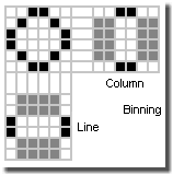
Line/column binning
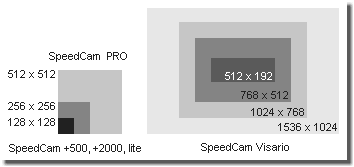
Comparison of SpeedCam read-out areas
Thus for instance SpeedCam +500/+2000/lite (Dalsa CA-D1-0128A, CA-D1-0256A CCD) use line binning, SpeedCam 512/PRO (EG&G Reticon HS0512JAQ CCD) use column binning and SpeedCam Visario (FhG/CSEM Cam 2000 Visario CMOS) uses format adjustment. For comparison of (maximum) resolutions, see the figure on the right.
Whereas binning keeps the field of view constant, and the saving
of pixels to be read out is done by reduction of resolution - lines
or columns are combined - with format adaption one saves pixels by
creating a pinhole effect. Binning makes images look more blurred,
format adaption makes them smaller, but with constant quality. In
the end it comes to the same thing: if one wants the same field of
view, one will have to edge closer or spread the image - the image
turns pixeled. Binning does this without changing the location or focus.
One cannot generally say what is better. During adjustment jobs
one will appreciate to avoid changes in lens and camera settings
(especially concerning exposure), when increasing the frame rate.
On the other hand, however, there will be advantages, when all the
images show the same resolution. In real format adaption is
preferred: quality counts. Of course, this process is also
supported by the increasing use of CMOS sensors, which are
predestinated for this by design.
Read out methods (interlaced, non-interlaced, progressive scan)
Existing read out procedures for sensor are somehow similar to displaying on screens. In the easiest case half frames like in the interlaced mode of the CRT TV are used. The human eye is to slow to recognize this trick. Not until the still frame replay one perceives this deceit due to the common comb style artifacts, see also [SloMo Freq.].
-
2:1 interlaced operation in frame integration mode: the first half frame consists of all odd lines the second half frame of all even ones. Both half frames are read out one after the other, but are displayed simultaneously. Disadvantage: one frame in real consists of two images with a time lap between them, which are mixed line by line. Lines 1, 3, 5 ... e.g. are from the present moment, whereas lines 2, 4, 6 ... yet show the image before. In the next step the even lines receive a new image, whereas the odd ones yet show the old one, and so on. Therefore this typical so called comb artifacts in animated scenes, the full frame resolution, however, is preserved.
(In case of deinterlacing for video replay comparable with »weave«.) -
2:1 interlaced operation in field integration mode: two lines are already summed up (binning) during the read out and are displayed, resp. So in the first half frame line 1 and line 2 give line 1, lines 3 and 4 line 2 and so on. In the second half frame line 2 and line 3 give line 2, line 4 and line 5 give line 4 and so on. Therefore the resolution is reduced, possibly there are block or stairs artifacts at edges. But the resolution in time is better, and so any motion blur is reduced.
(In case of deinterlacing for video replay rough comparable with »field averaging«.) -
Non-interlaced: half frames are made, which if necessary, are complemented to images with full resolution by doubling the lines. Often semi-professional (VHS/SVHS) video recorders can (could ;-) operate in this mode. Resolution may be lost, but the relation in time is clear.
(In case of deinterlacing for video replay rough comparable with »bob« (interpolation of missing lines in each half frame) or »skip field« (every second half frame is displayed only, its missing lines are interpolated), resp.) -
Progressive scan: the sensor is read out completely at (as far as possible) one certain time. Highest resolution in image and time. Technical sophisticated, but most productive method for high-speed imaging and motion tracking.
(There are no full images, so-called »frames« in traditional tv/video technique. Only half images, so-called »fields« are used.)
For high-speed cameras progressive scan is the most suitable approach. In the standard image processing sector (»machine vision«), however, the interlaced methods can provide reduced data rates and due to the double exposure and maybe a optimized fill-factor of the sensor they can increase light sensitivity.
Image memory
Buffer memory
Either the image data are gathered analogue or digital
due to the sensor design. Usually analogue image data are digitized
before storing, but there are exceptions. Normally the storage
takes place in some kind of buffer. Its location varies with the
state of the art and the demands for the camera and for the camera
system, resp.
Even the - of course, very limited - buffering of image data on
the sensor itself is possible. Especially in very fast
cameras.
If the data rate is small enough the image data can be directly
streamed to a storage medium (e.g. the harddisk of a notebook).
Therefore concerning real high-speed cameras worth of their name
this is not an option.
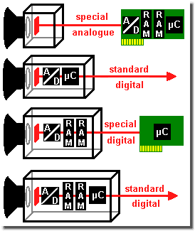
Digital high-speed camera concepts
Legend to the figure on the left: RAM = image
memory; µC = microcontroller or processor; A/D = analogue to
digital conversion (often already integrated in the sensor)
The green card should show a PC card, the red line connection
possibilities (image and control data).
The standard connection can be e.g. (Gigabit) Ethernet or
FireWire.
And so a crash-proofed digital high-speed camera interior may look, see [SloMo HYCAM].
Cameras without analogue/digital converter on the sensor chip or
inside the camera head transmit the analogue image data to the
control host and only now they are converted into digital values
and stored. That permits to keep the real camera head small and its
power consumption (waste heat!) is modest. The demands for the
cables, however, are comparatively high due to the analogue data
transmission. On the other hand digital cameras already convert the
data on the sensor chip or inside the camera head and store them
there preferably.
Because of the limited capacity the buffer memory is all the time
overwritten in some kind of endless loop. The trigger impulse
controls this process and the images are done - cut!
This buffer memory, which usually holds rather raw image data
without color recovery algorithms (therefore the expression RAW
format), is mostly built with DRAM (dynamic random access memory)
integrated circuits similar to those known from the memory banks of
PC main memory. With the typical feature of DRAMs to loose their
data during a power failure.
Memory ICs, which keep their data even without power supply, so
called NVRAMs, SRAMs, Flash (non volatile; Static RAM), are hardly
used for buffer memory due to different disadvantages like slower
speed, higher costs, higher power consumption, shorter durability,
...
One makes do with a safety (rechargeable) battery, which supplies
the buffer memory if necessary, or even with a full service
(rechargeable) battery holding the complete camera in working
order. Sometimes with an UPS for the complete camera system,
especially for systems, which buffer their data at first in the
control unit.
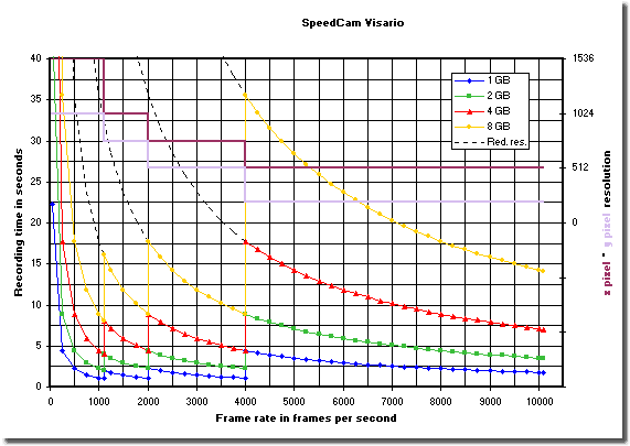
Image memory, resolution levels, frequency and recording
time
of SpeedCam Visario high-speed cameras
Explanation of the diagram on the right side:
The left axis defines the maximal possible recording time at given
frame rate. The right axis shows the maximal possible
x pixel × y pixel resolution in relation to the
frame rate. These reduction levels are drawn for better
comprehension.
The jumps in recording time derive from the reduction steps of the
resolution with increasing frame rate. If one voluntarily accepts
the reduction level through lower frame rates, one will be able to
drastically increase the recording time in parts. Then one moves
along the stroke-dotted lines. Perhaps in this case the recording
time may be limited by the minimum frame rate of the system. It is
about 50 frames/sec with SpeedCam +500 and SpeedCam PRO, and
reaches about 10 frames/sec with SpeedCam Visario.
(The markers in the curves are given to identify the curves in a
black-and-white print only. In real the frequencies can be selected
without steps.)
Permanent memory
Equality is between the buffer memory and a role of film
of traditional movie cameras. Its limited capacity forces to shift
the data to a mass storage medium. Here one often uses the hard
disk of the control unit and its optical disk or removable drive
and the network and the cloud, of course.
Some high-speed cameras own a harddisk or a flash card inside her
head. Concerning applications with high mechanic loads (e.g. usage
in a crash vehicle), however, at least the harddisk, even if it is
automatically parked during the trial, causes a rest of risk. Even
if several models are specified for the loads in a crash test -
when parked mind you.
These mass storage media in the camera head, however, can
accelerate the work in a considerable manner. One takes one
sequence after another in a short period, shifts the data to the
mass storage medium and during a break or over night one downloads
the data or just exchanges the storage medium.
Display and storage
Every manufacturer has its own philosophy presenting
the image data more or less revised. For instance with automatic
contrast or edge enhancement. Like in photography field
professionals prefer the access on RAW images. They are not
falsified and very efficient. For instance uncompressed AVI files
are by factor 3.5 to 4 bigger than RAW files.
At first one sees the (potential) images through various preview
or view finder channels, which may be processed by DSPs (digital
signal processor) in real time or be compressed by them. Often
simple sharpen, edge enhancement and color saturation filters are
used. Not to mention the defective pixel correction, i.e. the
interpolation of defect pixels by their neighbors.
For massive image processing in real time software is hardly to
use. Usually it operates with the data saved on the mass storage
medium and converts them to common file formats. Due to the
calculation time this may be even over night.
In spot checks of serial production of safety relevant devices the
image data are stored on durable media and archived. Concerning
air-bags, e.g. for ten years under the scope of product liability
law and additional three years to cover the juridical objection
period. In all thirteen years. A lot of material will gather
then.
